| | Description | The DRAGONFLY is not a general-purpose micro processor but rather a
flexible controller that can perform complex state-machines execution.
The aim of the DRAGONFLY is to make design of new IP blocks easier.
The DRAGONFLY implements a full instruction set. | | Documentation |  The DRAGONFLY 1 micro core (70 pages) The DRAGONFLY 1 micro core (70 pages) | | Latest Version |  dragonfly-1.2.tar.gz (Updated: 2002 May 31st) dragonfly-1.2.tar.gz (Updated: 2002 May 31st)
 Please see the ChangeLog file for modifications Please see the ChangeLog file for modifications | | Licence(s) | GNU Lesser General Public Licence (LGPL) (for the VHDL source code) | | Author(s) | The LEOX team | | Related Link(s) | none | |
The DRAGONFLY micro core has been designed as a small (less than 4K gates), fast and programmable core, to be used in an ASIC or a FPGA, in areas such as serial communication management (UART, Smart cards controllers, LDC drivers, I²C controllers, SPI controllers), on-chip test and debug of complex blocks, intelligent DMA, FLASH controllers, audio-rate SDRAM controllers, and so on. The advantages of having a programmable core on an ASIC to perform complex tasks are obvious: - writing and debugging software code is faster than designing the same function in hardware.
- it is possible to reload the software in the ASIC, to correct bugs or change the functionality.
The Dragonfly core however, is not well suited to be used as a general purpose processor. It has no interrupt mechanism (this has been chosen for simplicity of implementation), and as such it can't handle true real-time tasks (those tasks should be handled inside a peripheral if needed). The core has no multiply/divide instruction, and its arithmetic capability are basic. The philosophy behind the core is that, real-time and complex arithmetic tasks are handled inside adapted peripherals (serial interfaces, FIFOs, Arithmetic operators, Timers, etc.), while the core itself is responsible for peripheral configuration, data motion and interpretation, complex state machine emulation, complex decisions calculations. Writing software for the DRAGONFLY is done using a simple, easy to use and easy to learn assembly language. Available software tools are: - a complete macro assembler (that runs on Linux, Solaris and Windows).
- an Emacs mode for easy assembly code edition.
- a tcl/Tk based debugger to be used (only) with the Modelsim VHDL simulator.
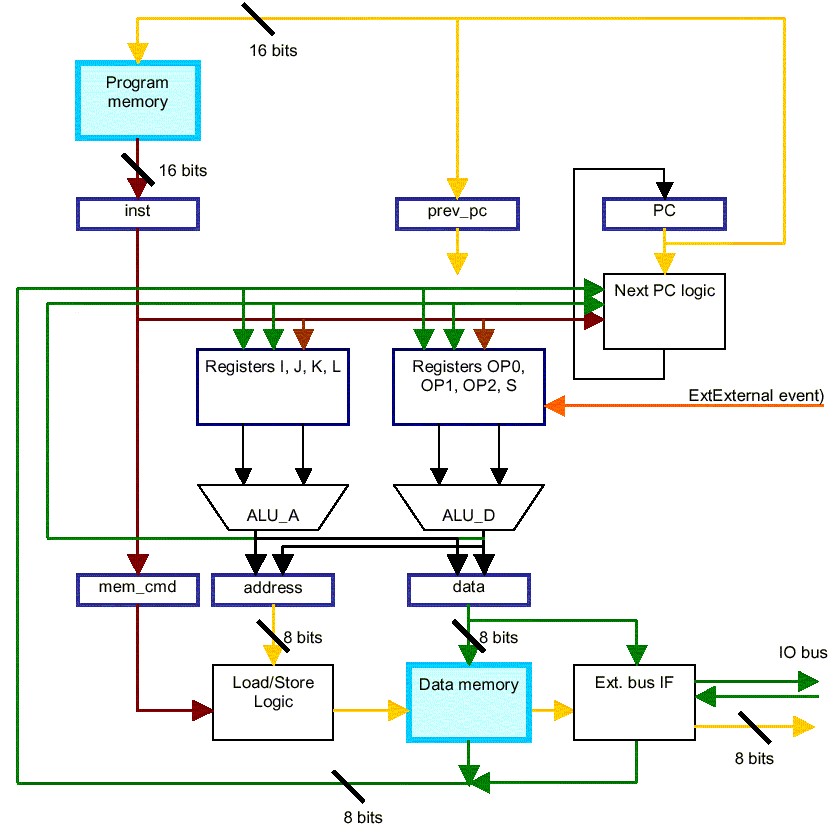
Description of the DRAGONFLY micro core The DRAGONFLY core is a simple 3 stage pipeline with a true Harvard-like architecture (data and program memory are separated and accessed in parallel). Instructions are 16 bits wide, while data are only 8 bit wide. The DRAGONFLY implements a full instruction set such as: - ALU operations.
- Shift operations.
- Bit operations.
- Branch operations.
- Data Transfer operations.
- FIFO operations.
- Simplified Mnemonics.
- Low power and sleep mode.
First stage of the pipeline is program memory access, second stage
decodes the instruction and execute it, third stage is data memory
access.
As a consequence of this architecture, the data in memory are
accessed by LOAD instructions with 1 cycle of latency, while most
instructions are allowed to store directly their result in memory
with no latency.
The DRAGONFLY has 2 set of registers : - the address registers (I, J, K, L)
- the ALU registers (OP0, OP1, OP2)
Most instructions allows parallel access to both set of registers,
for instance it is possible to compute an ADD between 2 ALU
registers, and simultaneously to access and modify an address
register to compute the address where the result will be stored. |  | | DRAGONFLY: Architecture Overview |
| | |
| Address registers are 8 bit wide and are used to generate address to access data memory. So the data memory can have at most 256 locations. If more memory is to be used, one must implement a paged memory access with a page register mapped in the IO space. ALU registers are 8 bit wide but have been designed to manipulate 16, 24 and 32 bit data efficiently. The registers can be used as "normal" registers, but also, they can be used as 4 bytes FIFOs that holds up to a complete 32 bit word. Once in the FIFO, a multi-byte word can be manipulated with most ALU operation, one byte at a time. S register is the status register and holds 8 status bits. Program memory access is done through 2 combined registers: a 11 bits PC, and a 5 bits page selector PG. The PG register gives the 5 MSB of the instruction address, while the 11 LSB are given by the PC. This gives up to 64K accessible instructions.
The PC is automatically incremented each cycle, and can be changed by either relative branch or absolute jump instructions. However, PG is not automatically modified, so for instance the PC may wrap around from 7FF to 000 without affecting the page number.
PG can be changed only with the SNP ("set next page") instruction, combined with a JUMP instruction.
The 11 bits of the PC plus the 5 bits of the PG can be saved/restored from memory to implement function call and return through different pages. No interruption mechanism exists, but the Ex bit in the S register can be used to signal the occurrence of an external event (however it must be tested explicitly by the program). An external IO bus, separated from the data memory bus and accessed through IO LOAD and IO STORES links the DRAGONFLY to its peripherals. How to run the testbench using Mentor Modelsim simulator Unarchive the downloaded file. Thus, you should get a dragonfly-1.2 directory with everything inside. - tar xzvpf dragonfly-1.2.tar.gz
Launch the gui of the Mentor Modelsim simulator: - vsim - gui
- Change the working directory to dragonfly-1.2
If you don't have a work library defined, do it now on the Modelsim console: If you are on a PC computer, edit the file dgf.do and change the line: exec dgfas_sun -h -g "$test_name.dgf"
to
exec dgfas_pc.exe -h -g "$test_name.dgf" Note: under Linux, replace dgfas_sun by dgfas_linux On the Modelsim console, type the following command: The core is compiled, and simulation is started.
Run the simulation for some time.
Give a look to the debugger window, try to move forward/backward.
You are done! How to change the software being tested Modify the following line into the dgf.do file: set test_name test_dgf_branch_op Note: test_name is the tcl variable holding the name of the *.dgf file to be compiled and run. How to install the DGF mode under Emacs Add the following lines to your .emacs file: (load "/YOUR_HOME_DIR/dragonfly-1.2/dgf.el")
(setq auto-mode-alist (append '(("\\.dgf$" . dgf-mode)) auto-mode-alist)) Note: Replace YOUR_HOME_DIR by the name of your home directory. Thus you will get a new DGF item inside the menu bar of Emacs while editing a DGF source file. How to compile a DGF source file - Edit your DGF source file under Emacs
- Inside the DGF item of the Emacs's menu bar, define assembler path
- Use the DGF subitems to compile your source file and to generate the appropriate output files.
| 


 Please see the

